Hardware
The hardware was constructed on a breadboard for testing, then the schematic was created in Eagle and
a circuit board manufactured. All the ICs on the board are mounted in sockets.
Input power is provided from 3 AA batteries, provided through a 2-pin header. The batteries are contained
in a standard plastic 3-cell holder. The holder is mounted to the inside of the case with a Velcro strip.
Voltage regulation is done by a REG102 low-dropout regulator, providing +3.3 VDC.
The microcontroller is a Parallax P8X32A (Propeller) in the –D40 package, with the program stored in a
24LC512 Serial EEPROM.
A 4-pin header provides connection to a Sensirion SHT11 sensor mounted on a remote board. The remote
sensor board is drilled to allow use of the Sensirion SF1 Filter Cap. This cap mounts over the sensor
and provides protection while still allowing relative humidity measurements. The board is mounted so that
only the cap extends through the top of the case, and is sealed with a little Sugru.
The XBee Wireless RF module is mounted in the required 2mm sockets. It is an Xbee 2mW Series 2.5 Chip Antenna.
When I purchased another unit recently for doing some breadboarding, I purchased this as
Xbee 2mW PCB Antenna - Series 2 (ZigBee Mesh). The XBee was configured using the Digi X-CTU configuration
software and set as ZNET 2.5 ROUTER/END DEVICE AT. The XBee ‘SLEEP_RQ’ pin is wired to the Propeller, so that
the XBee may be put into low-power mode when not needed.
Software
The program first initializes the communications with the XBee (Simple_Serial). A cog for reading the
SHT11 is launched, and a cog for data transmission is started. The main program then ends.
cog_Temps
When this cog is launched it starts the SHT11 object (Sensirion_full), then takes a temperature/humidity
reading and stores this info in Hub memory.
cog_Send
At startup of this cog, the XBee ‘sleep’ pin is taken low to wake up the XBee module. After a short delay
to allow the XBee to get ready, a function is called which transmits the temperature and humidity values
stored in the Hub memory. After another short wait, the XBee pin is driven high to put the XBee into a low-power
mode. Once the XBee is sent to sleep, the ‘cog_Temps’ cog is stopped, and a function is called that drops
the Propeller into a low-power mode (running at 5 MHz with no PLL). A loop is entered which counts up to
600 seconds (10 minutes). At the end of the count, the Propeller is returned to 80 MHz with PLL operation,
and the ‘cog_Temps’ cog is restarted to take a temperature/humidity reading. The XBee is then taken out of
low-power mode and the temperature/humidity data is sent. The system is returned to low-power mode (as before)
and the 10-minute countdown starts again.
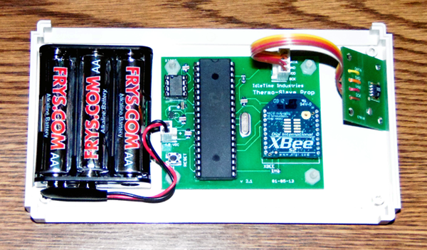
Thermo-Slave v2.1 components
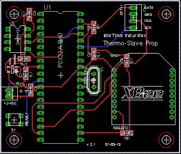
Thermo-Slave v2.1 circuit board layout
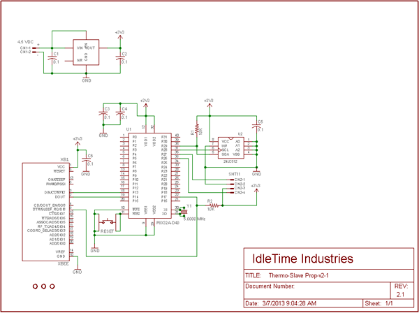
Thermo-Slave v2.1 schematic
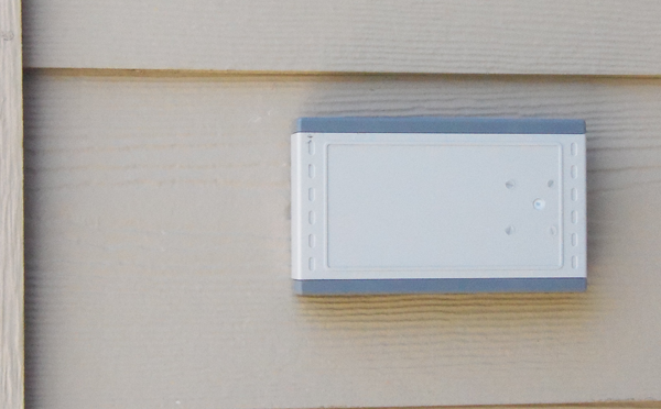
Thermo-Slave mounted on outside wall
Thermo-Prop
![[ Home ]](images/HomePage.png)
Last updated: 14 Feb 2014
Web Author: John Locke
Copyright © 2014 IdleTime Industries - ALL RIGHTS RESERVED