Hardware
The hardware was constructed on a breadboard for testing, then the schematic was created in Eagle
and a circuit board manufactured. All the ICs are surface mount devices.
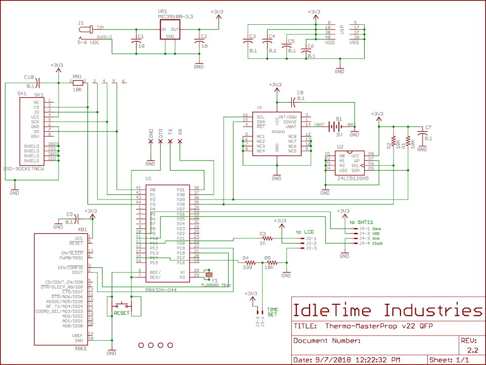
Input power is provided from a ‘wall wart’-type adapter, providing 5 VDC through a standard 2.1mm DC plug.
Voltage regulation is done by a MIC39100-3.3 regulator providing the +3.3 VDC to power all circuits.
The microcontroller is a Parallax P8X32A (Propeller) in the QFP surface-mount package, with the program
stored in a 24LC512 Serial EEPROM. Pads are provided on the edge of the circuit board for programming the EEPROM.
A DS3231 Real-Time Clock keeps track of the current date and time, and is battery-backed with a
BR1225 Lithium coin cell battery.
A Sensirion SHT11 temperature/humidity sensor is connected to the pcb via a 4-pin header to provide local temperature and
humidity data.
The XBee Wireless RF module is mounted in the required 2mm sockets. It is an Xbee 2mW Series 2.5 Chip Antenna.
When I purchased another unit recently for doing some breadboarding, I purchased this as
Xbee 2mW PCB Antenna - Series 2 (ZigBee Mesh). The XBee was configured using the Digi X-CTU configuration
software and set as ZNET 2.5 COORDINATOR AT.
Connection to the LCD is provided via a three-pin header. The LCD is a 4-line by 20-character format, with a Sparkfun Serial Enabled LCD Backpack.
A two-pin header provides a connection for the pushbutton (normally open) switch. The pushbutton switch
input to the Propeller is pulled to ground via a 10K resistor, and goes high upon switch closure.
The pin is current-limited via an inline resistor. A small tactile pushbutton is also soldered to the
pcb which provides a RESET function for the microcontroller, when pushed.
Software
The main program first initializes the communications (FullDuplexSerial4port), then inits the LCD display.
The real-time clock (DS1307_RTCEngine) cog is started and the time is read and stored. Next, cogs are
started that read the temperature/humidity (uses Sensirion_full), monitor XBee communications,
monitor the pushbutton, and write to microSD (uses fsrw). The program then enters a loop that monitors
various flags (SettingRTC, NewOutTemp, NewDwnTemp, NewLocTemp) and calls subroutines based on the state
of the flags. It also updates the time display once a second.
cog_LocalTemp
This starts the cog for reading the SHT11, which then takes a reading from the sensor every 5 seconds.
After storing the temp/humidity data, a flag ‘NewLocTemp’ is set, indicating to the main program loop
that the LCD should be updated.
cog_Remote
This cog monitors the XBee ‘receive’ line for incoming data. The incoming data is identified by the first character received:
| First Char | Message |
|---|
| D | the transmission is from the downstairs XBee. The rest of the transmission is parsed and stored as the downstairs temperature and a flag is set ‘NewDwnTemp’ to indicate that the main loop needs to update the downstairs temperature displayed. |
| |
| T | this is a request from the downstairs unit for the current date/time and outside temp. A function is called to send the requested data. |
| |
| O | this is a transmission from the outside unit. The temperature and humidity are parsed from the data string and stored, and a flag set ‘NewOutTemp’ to indicate to the main loop that the outside information has updated. The upstairs temperature is sent to the downstairs unit before resuming. |
cog_Log
When this cog is launched, it retrieves the date/time info and uses that information to produce a filename in the format
"yy-mm-dd.csv". The microSD card is mounted and a file opened. A header indicating “=== REBOOT ===” is
written before the standard data header. This indicator is only written at cog initialization and can be used to see
that the system restarted for some reason. The cog then enters a loop monitoring the current date/time. On the
quarter-hour, the drive is mounted and the current data is written to disk. Each midnight, a new file is opened for
that day’s data collection. A data header is written at the top of each new file.
cog_Button
This cog runs in a loop waiting for a button press. When a button press is detected, the cog sets a flag
‘SettingRTC’ to indicate to the main loop that the time-setting function should be called. The time-set
routine uses short button presses to increment the current variable (year, month, day, etc) and long button
presses to indicate that the current data is correct and to move to the next variable (after setting year,
moves to setting month, etc).
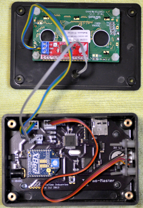
Thermo-Master v2.2 components
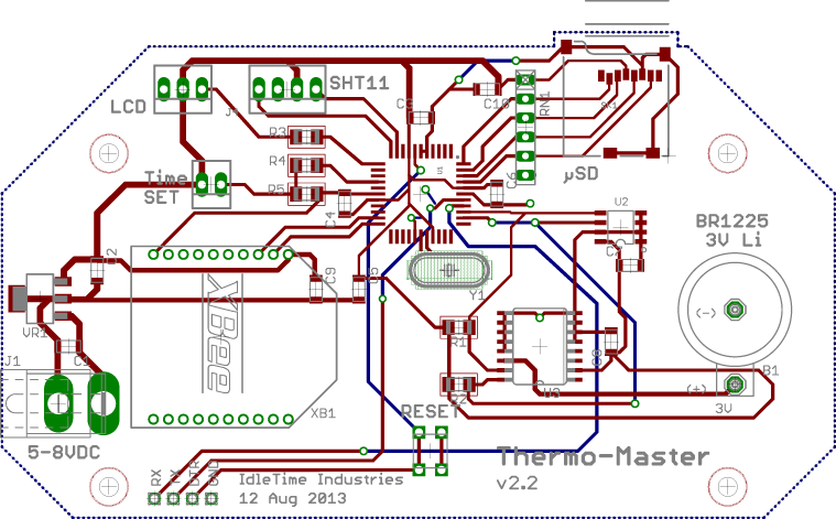
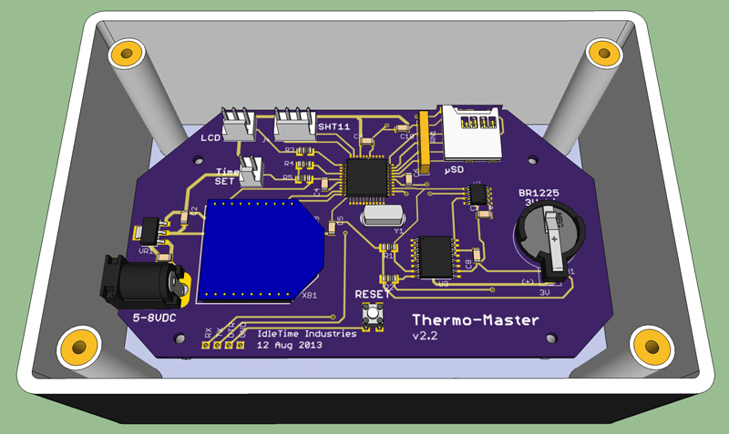
Thermo-Master v2.2 circuit board layout
Thermo-Master v2.2 schematic
Thermo-Master v2.2
Thermo-Prop
![[ Home ]](images/HomePage.png)
Last updated: 14 Feb 2014
Web Author: John Locke
Copyright © 2014 IdleTime Industries - ALL RIGHTS RESERVED