Goal Light and Horn
Project
My 12-year old grandson loves to play hockey, and plays lots of street hockey and knee hockey with his buddies when not on the ice.
I found he was using goal horn sound clips off his iPhone and one of my Veho battery-powered speakers to celebrate goals when
playing. This project was to provide him with not only his goal horn, but a choice of 3 different sound files that may be triggered,
and a flashing red light to provide the full hockey experience!
Hardware
My original thought was to design a full custom circuit board to provide the ‘brains’, but after further reflection, I decided
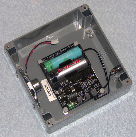
instead to design a board to plug into one of the many Parallax P8X32A QuickStart boards I seem to have accumulated. The designed plug-in
pcb accepts approx 7.4 VDC input from a Parallax Li-ion power pack. The power pack includes 2 18650 li-ion cells (3.7 VDC each) with
proper charging circuitry. The custom board powers the QS (QuickStart) by providing approx. 4.7 VDC on the VIN pin (pin 40).
The Goal Light & Horn custom board uses the 3.3 VDC returned from the QS regulator (on pin 38) to power the µSD card interface
and the relay.
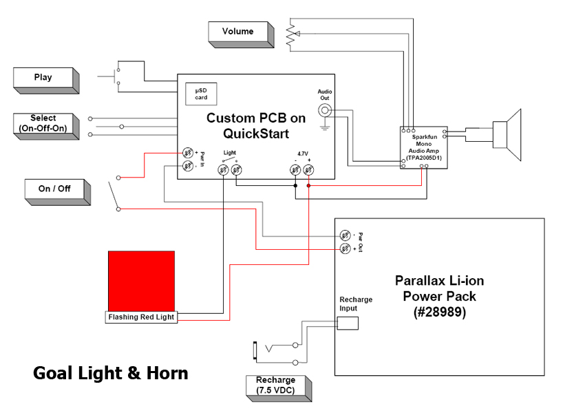
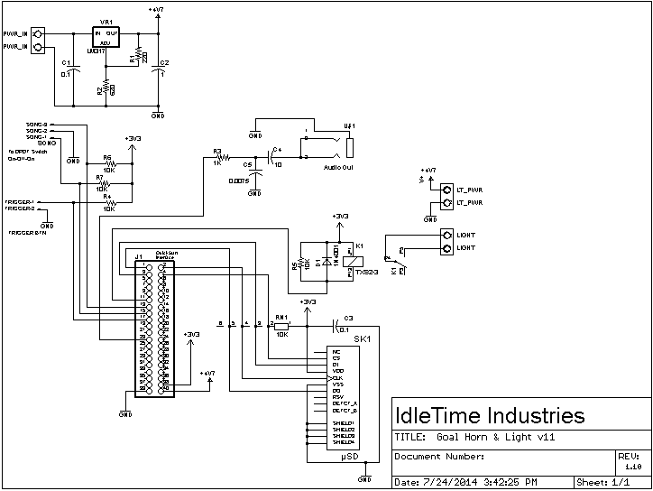
Goal Light and Horn Block Diagram
Onboard the Goal Horn & Light pcb is an LM317 voltage regulator, dropping the battery input to approximately 4.7 VDC. The odd
voltage value was chosen due to the voltage requirements on a sticker on the bottom of the red light assembly, although it
probably would run off 5 VDC with no problem. This voltage is provided to the QuickStart board on the VIN pin (pin 40).
The QuickStart board regulates this voltage to 3.3 VDC and makes that voltage available on pin 38. The 4.7 VDC is also
provided to a screw-terminal connection for external wiring to power the audio amplifier and the flashing light assembly.
A µSD socket is powered by the 3.3 VDC and connected to Propeller pins P0-P3. A 10K pull-up is provided on the lines.
A DC relay is driven by Propeller pin P10. The relay is a Panasonic DPDT (3V, 16.7 mA) and is driven directly by the Propeller.
The line is pulled high via a 10K resistor, as well as the resistance of the relay coil. A screw-terminal connection
provides access to a set of Normally Open contacts on the relay; used to activate the flashing light. A 3.5mm stereo audio
jack provides the audio stream from the Propeller (pin P20); read from the µSD card. This audio needs further amplification
to be of use.
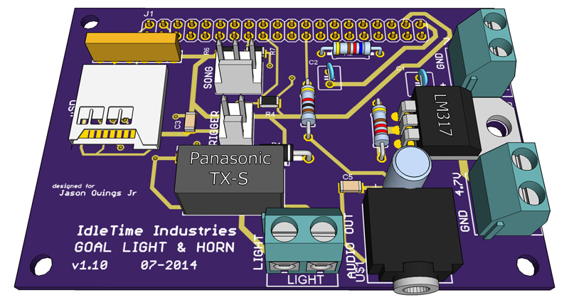
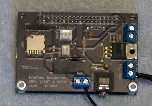
Goal Light & Horn circuit board
For the audio amplification, a
Sparkfun Mono Audio Amp module is used. This small board utilizes a Texas Instruments TPA2005D1
Audio Power Amp chip. The module has connections for power in, volume control, audio in, and audio out. The TI chip is a
1.4-Watt Class-D power amplifier. It utilizes a PWM-like output, which is clocked at 250 kHz. The speaker effectively ‘filters’
this signal back into audio frequencies. A 4-ohm 2W speaker is in the box, and a 10K logarithmic-taper potentiometer is provided for
volume control.
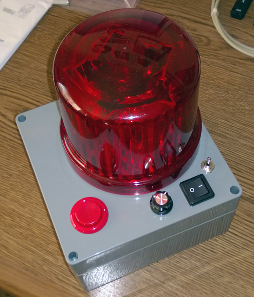
Other external assemblies include a DPDT (on-off-on) toggle switch to select one of three ‘songs’ to be played, a rocker
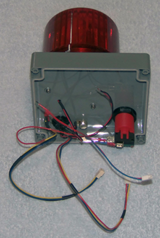
SPST switch for power on-off, and a large, red, arcade-type button to trigger the action. I purchased the 'rotating' red light
assembly from Amazon. The box itself is heavy-duty plastic.
Software
The software for this project is rather simple. The main program first initializes the WAV-player object (V2-WAV_DACEngine.spin),
then enters a loop waiting for the 'Trigger' button to be pressed. The button press is debounced in software. Then the position of the
3-position toggle switch is decoded and used to decide which of 3 WAV files from the µSD card (Song1.wav, Song2.wav, or Song3.wav) is to
be played. Along with the WAV file playing, the relay output is switched for 10 seconds, causing the red light to flash for that time.
![[ Home ]](images/HomePage.png)
Last updated: 26 Nov 2014
Web Author: John Locke
Copyright © 2014 IdleTime Industries - ALL RIGHTS RESERVED